UTM Stormwater Management Pond

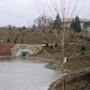
The Erindale Campus of the University of Toronto was originally constructed in the late 1960’s which preceded concerns over the control and treatment of stormwater runoff. With major expansions to the Campus since the completion of the 2000 Master Plan, there has been pressure on the University to implement a comprehensive Stormwater Management Plan, as opposed to relying on numerous development specific SWM measures.

The Master Drainage Plan for the Campus recommended an ‘end of pipe’ facility (pond) to accommodate the water quality and erosion control objectives for the site. This pond was to be located within existing parking areas near the location where the storm drains flow into the Credit River. As a result, the parking area required reconfiguration and the natural heritage ecology of the valley needed to be incorporated into the pond design.

MGM Consulting designed the pond to service the 54.51 ha of storm catchment. The Enhanced Level controls required the provision of 6,123 m3 of permanent pool and 2,180 m3 of extended storage to service the erosion control criteria. The design includes a diversion structure that allows diversion of storm flows during maintenance operations. The weir gate also allows researchers to control flows to the pond to examine the impacts of full flow through scenarios as opposed to flows limited to first flush events.

Reducing Site Costs By Going Green

 
In addition to the emergence of LEED Certification over the last number of years, municipalities and conservation agencies have set sustainable planning objectives for new developments with a push towards “Low Impact Development” (LID) requirements. LID strategies emphasize the use of natural or engineered stormwater controls to mimic the natural hydrological cycle. The main goals of the LID initiative is to reduce stormwater runoff volumes and rates, reduce pollutant loading to downstream municipal sewers and receiving waters, recharge groundwater and to provide water conservation.


There are several LID practices available which range in both cost and effectiveness. It is also important to note that some practices provide more than one benefit. For example, permeable pavers will reduce peak flows, reduce runoff volumes and trap sediments which improve the quality of stormwater runoff. A bio-swale and infiltration pit feature would provide the same benefits more cost effectively, but may not be appropriate due to space limitations or soils conditions. Selecting the appropriate LID practices can speed up approvals, and often reduce site servicing costs by eliminating portions of the traditional site drainage features (catchbasins and storm sewers). Combining LID practices and incorporating them into the overall stormwater design by working back from the most economical practice will reduce the overall cost associated with the servicing component of a project.


A recent Fire Station project completed by MGM included a centralized bio-swale surrounded by a strip of permeable pavers within the parking lot with an infiltration pit constructed below. These three separate LID practices constructed together achieved multiple stormwater objectives within a single footprint. The upper bio-swale area provided both a portion of the required storage volume during a 100 year storm event as well as a quality component for sediment and phosphorus removal. The infiltration pit below the bio-swale provided the majority of the required water balance component. The small strip of permeable pavers constructed along the edge of the bio-swale was installed to achieve the remaining water balance requirement. The philosophy was to maximize the design value of the less expensive infiltration pit and bio-swale while minimizing the required area of the more expensive permeable pavers to achieve the municipality and conservation authority objectives.


In some situations where site conditions are favourable, implementing LID practices can result in a more economical approach than the traditional site servicing designs that were required before sustainable planning objectives were introduced. These economies are only realized when the proper engineering principles are applied to optimize the design. For example, drainage swales were traditionally required to be graded with a minimum of a 2% slope while bio-swales and enhanced swales can be graded as low as 0.5%. The reduction in slope allows for a longer contact time for runoff which assists with pollutant removals. The slope reduction also provides more latitude in the grading design which could reduce earthwork costs as well as servicing costs by reducing the number of storm structures.


MGM recently reviewed a functional engineering report at the request of a developer due to unanticipated site work costs. The functional design was for a 17 hectare industrial development which included a traditional storm system for drainage conveyance. LID practices were not required for this particular development and as a result were not employed into the functional design. The report indicated that an extensive amount of engineered fill would be required due to grading constraints at the perimeter of the site. MGM redesigned the site by incorporating a bio-swale with an overflow storm system along the rear of the property. The redesign allowed for the majority of the rear parking lot to drain via sheet flow to a perimeter bio-swale therefore eliminating a large portion of the storm conveyance system. The decreased bio-swale grades reduced the grading constraints which allowed for the finished floor to be lowered by 1.0m eliminating the requirement to import fill. Incorporating LID strategies into this particular project drastically reduced servicing and grading costs, increased the marketability of the development and was supported by the approval authorities which assisted in expediting permits.


For more information on this topic and how it could relate to your project, contact MGM directly.


Using Bioswales for Passive Stormwater Treatment

 
Bioswales are one of several passive options available to meet the stormwater management objectives for a development which and can be located wherever traditional landscaped areas are proposed. They are typically located within traffic islands or adjacent to parking lots. Bioswales provide both a water quality and water balance component and are often the preferred choice of developers due to the relatively low cost in comparison to alternatives. Bioswales consist of a filter bed which is a mixture of sand, fines and organic materials with a recommended bed depth between 1 and 1.25m. A 75mm mulch cover is recommended over the filter bed to enhance plant survival, reduce weed growth and provide pre-treatment of the filter bed. Contributing drainage areas directed to bioswales should range between 100 square meters to 0.5ha and should be designed with a level surface to encourage stormwater to spread out evenly over the surface. Pre-treatment of drainage with a vegetated filter strip, or a rip-rap diaphragm, often precedes the bioswale to dissipate the flow and remove particles that could clog the filter bed, reducing maintenance.


Depending on the proposed functionality of the bioswale, the landscape architect will specify drought resistant or water tolerant plants or native grasses. Coordination with the landscape architect is important during the design stage as the proposed planting is critical to the function and appearance of the bioswale and will determine the level of ongoing maintenance required. As bioswales are designed to capture small storm events, an overflow or bypass is necessary to redirect the less frequent storms to the storm sewer system.


As stated above, bioswales can be located wherever traditional landscape areas are proposed but there are design considerations required to overcome site specific constraints. Some of the major constraints are listed below:


  • Stormwater runoff from fuel sites or some industrial operations have the potential to contaminate the existing soils and water table. Additional measures such as impermeable liners are required to ensure runoff is not infiltrated but held within the voids of the filter bed and taken up by the plants.
  • An improperly designed sub-drain system could result in standing water within the bioswale. Designers should target a 24 hour drawdown to eliminate the potential for mosquito larvae.
  • The Ontario Building Code requires a 4.0m setback from buildings to ensure building foundation drainage is not impacted and a minimum of 1.0m is required above the seasonally high water table to reduce the potential failure of the bioswale.
  • In order to achieve a water balance component, native soils must meet the municipality’s minimum percolation rate requirements.


Bioswales have been shown to provide a water balance component by reducing runoff volume through evapotranspiration and infiltration. Factors that can impact water balance benefits are native soil infiltration rate, rainfall patterns, and sub-drain sizing criteria. The quality component is provided by the removal of pollutants as a result of sedimentation, filtering, soil adsorption, microbial processes and plant uptake. It is also important to note that there is a direct benefit relationship between the water balance and water quality functions provided by the bioswale. The percentage of runoff infiltrated or taken up by the plants is equivalent to the reduction of pollutants leaving the site. Other benefits include reduced thermal aquatic impacts and reduced urban heat island effects.


A properly designed and constructed bioswale provides a cost effective and sustainable solution that assists in achieving stormwater management objectives.


References

Low Impact Development Stormwater Management Planning and Design Guideline, 2010

Toronto and Region Conservation, Credit Valley Conservation


For more information on this topic and how it could relate to your project, contact MGM directly.


Site Sediment and Erosion Control Requirements

 
Clearing and grubbing of land during the construction process results in the loss of vegetative cover. The loss of this cover and the loss of stable topsoil during the site stripping process leave the underlying soils vulnerable to the erosion process. The exposed soils are subjective to wind forces that reduce air quality control. During rain events, the soils are transported downstream impacting aquatic habitats as well as infrastructure.


In 2006, The Greater Golden Horseshoe Area Conservation Authorities prepared a guideline entitled “Erosion & Sediment Control Guideline for Urban Construction”. Based on the guideline, all projects involving the removal of topsoil or site alteration requires an ESC (Erosion and Sediment Control) Plan in place prior to commencing construction. Failure to adhere to the plan could lead to the potential for prosecution under the various pieces of environmental legislation.


The following principles assist in creating an effective ESC Plan.

(Ref. Erosion and Sediment Control Guidelines for Urban Construction)


Adopt a multi-barrier approach to provide erosion and sediment control through erosion controls first.

Retain existing ground cover and stabilize exposed soils with vegetation where possible.

Limit the duration of soil exposure and phase construction where possible.

Limit the size of disturbed areas by minimizing nonessential clearing and grading.

Minimize slope length and gradient of disturbed areas.

Maintain overland sheet flow and avoid concentrated flows.

Store/stockpile soil away (e.g. greater than 15 meters) from watercourses, drainage features and top of steep slopes.

Ensure contractors and all involved in the ESC practices are trained in ESC Plan, implementation, inspections, maintenance, and repairs.

Adjust ESC Plan at construction site to adapt to site features.

Assess all ESC practices before and after all rainfall and significant snowmelt events.


The guideline stresses that prevention of erosion is the preferred mitigation measure for reducing the potential for sedimentation.


Erosion and sediment control measures can be categorized as Erosion prevention controls and Sediment controls.


Erosion controls include minimizing the reduction in vegetative ground cover or immediate stabilization of disturbed areas by top soiling, seeding, sodding, mulching, erosion control blankets, etc.


Sediment Controls are further broken down into Perimeter Controls, Settling Controls and Filtration Controls. Some major perimeter controls include silt fences, cut-off swales and mud-mats. Settling controls reduce run-off velocity allowing the soil particles to settle out. Settling controls include sediment traps, rock check dams, straw bales and sediment control ponds. Filtration controls are achieved by filtering silt laden water through the use of a filer media such as a geotextile or sand. Filtration controls include storm inlet filter cloths, sediment bags and filter rings.


It is the responsibility of all Project Managers to ensure they understand the approved ESC Plan for their site and ensure its implementation to avoid both on-site and off-site environmental impacts.


For additional information on this topic, contact MGM directly.


The Practicality and Cost Effectiveness of Infiltration Trenches

Infiltration trenches are shallow surface or subsurface excavations lined with filter fabric and filled with clear stone which provide temporary retention within the stone voids until the stormwater can percolate into the ground. Trenches are typically sized for more frequent storm events and provides treatment for first flush storms which are high in sediment loading and pollutants.


There are several advantages to employing an infiltration trench into your stormwater management design. Reduction in volume runoff, mitigation of downstream flooding, smaller storm sewer sizes, removal of sediment and groundwater recharge are all elements provided by a properly constructed infiltration trench.


The subsurface trench is the type of trench typically employed in commercial and industrial type developments. This type of trench allows for pre-treatment practices such as oil/grit separators, enhanced swales, filter strips or bio-swales which reduce the amount of sediments entering the trench thereby extending its service life.


With the emergence of LEED and Low Impact Development objectives, infiltration trenches are being employed as an economical solution to meet both water balance requirements and stormwater drainage retention. The alternative best management practices to meet these objectives are grey water systems which re-use the stormwater, large ponds which provide evaporation and bio-swales which re-use the water through the plants. The disadvantage with the grey water system is that it’s cost prohibitive. The implementation of ponds and/or bio-swales provides some benefit but they need to be employed with other measures to meet the overall water balance objectives.


The practicality of the infiltration trench makes it the most practical measure to meet water balance objectives but there are often site constraints that limit its effectiveness or applicability. Site specific factors such as soils, water table location, depth to bedrock, type of development, and the proximity to wells or foundations will dictate whether or not an infiltration pit is feasible for the site.


There are several design considerations that can be employed to overcome some of the above noted site constraints. For example, increasing the trench footprint will allow you to reduce the trench height without reducing the required volume but will provide the allowable drawdown time in less favorable soils.


Every site has unique characteristics and requires a thorough stormwater analysis to minimize servicing costs while achieving stormwater objectives.


MGM has successfully designed numerous infiltration trenches throughout Southern Ontario.


For additional information on this topic, contact MGM directly.


On-site Wastewater Treatment Systems

 
On-site sewage treatment systems are used throughout Ontario to safely treat and discharge wastewater from a variety of sources in rural and less populated areas throughout the province. There are more than 1.2 million on-site systems in Ontario with most of these systems providing treatment for residential and smaller commercial and institutional developments such as schools, churches, restaurants and campgrounds.

Smaller on-site systems, (less than 10,000 L/d of flow) are regulated by Part 8 of the Ontario Building Code (OBC). Review and approval is completed by local building departments under the Chief Building Official.

Under the OBC the following conditions must be met.
• Building permit is required if constructing, altering or extending the system.
• Design flow based on building occupancy, fixture units & size, and
• Systems must be in the same property as where the sewage is generated
The OBC describes a set of minimum standards (now referred to as acceptable solutions) that regulate the size, design and layout of an on-site sewage treatment system. The purpose of the minimum standards set by the OBC is to protect human health and the environment. An improperly designed or constructed on-site system can cause significant environmental degradation as well as pose a risk to human health by contaminating drinking water or polluting surface waters.

There are many considerations that must be examined when designing an on-site system. These include, but are not limited to the following steps:
• Conducting a site evaluation
• Determining the total daily design sanitary sewage flow
• Choosing the type of pre-treatment system, and
• Choosing the type of soil absorption system.
Site evaluation, although only briefly mentioned in the Ontario building code, is one of the most important steps of the design process when designing and constructing on-site wastewater systems. The design of an on-site sewage system must be tailored to each individual lot, and the constraints and criteria of the building it is serving. According to section 8.2.1.2 of the OBC, a site evaluation must be conducted for every site where a new or replacement sewage system is to be installed. Consideration must be given to:
• Lot size and area available for on-site system,
• Usage/occupancy of the property
• Separation distance- horizontal and vertical
• Topography and flooding potential, and
• Soils and subsurface conditions
Soil is a vital component of any on-site wastewater treatment system, since the soils are responsible for majority of treatment of effluent in conventional septic tank/leaching bed systems. The type of soil will dictate if the site can accommodate an on-site system, how large the system will be and what type of systems are appropriate.

Soils receiving effluent must be unsaturated for a depth of 90 cm below the point of contact to ensure aerobic treatment. If the site cannot meet the 90 cm vertical clearance distance required with existing soils, the system will need to be raised above grade by using imported material. Therefore, it is necessary to be able to assess soils for the seasonal or fluctuating high ground water level.

A septic tank is the most common type of pre-treatment unit used in Ontario, and may be used in conjunction with an in ground or raised absorption trench leaching bed or filter bed. The primary function of a septic tank is to separate the solids from the liquids and provide storage for solid material. Septic means “without oxygen” describing the environment in a septic tank. Bacteria present in a septic tank are a type of anaerobic bacteria, and they break down sewage and sludge in the tank. The septic tank achieves approximately 10-20% of the total treatment of a conventional on-site system.

The septic tank performs the following main functions:
• Separation of solids and liquids
• Storage of sludge and scum
• Anaerobic digestion of sludge
Effluent filters are now mandatory on all new septic tank installations (implemented on December 31, 2006)

Secondary and tertiary treatment units provide an aerobic environment for treatment of sewage, which greatly improves treatment over a conventional septic tank. Depending on the type of treatment unit chosen, they may also provide an opportunity for some nutrient removal as well as some pathogen reduction

Secondary and tertiary treatment units are gaining popularity in the province and are now used in an estimated 10-20% of all new installations in the province.

Increasing cost competitiveness with conventional systems due to rising cost of granular materials also make alternative treatment systems more attractive for property owners.

As with available area, costs are also site specific. All of the tertiary units have approximately the same base price (around $10,000-$20,000). Secondary treatment may cost slightly less.

There are a number of soil absorption systems which may be used in Ontario. The type of soil absorption system used depends both on the results of the site evaluation, i.e. what the native soils are like and like how much space is available and also on the type of pre-treatment used.

The leaching bed is able to treat wastewater to a high degree by maintaining an aerobic environment within the soil matrix below the absorption trenches.

It’s important to maintain the aerobic environment in the leaching bed, or else the proper amount of treatment will not take place and untreated wastewater will be returned to the ground/ surface waters. Conventional type leaching beds can be designed as absorption trench systems or as filter beds.

Conventional absorption trenches consist of individual runs of perforated plastic distribution pipe contained within a trench of clear stone. The trenches are separated by native or fill soils. Distribution to the trenches is via either a distribution box or header pipe.

Leaching beds constructed and fill must follow all the design and code requirements outlined in the previous section, as the additional design considerations outlined in section 8.7.4.2. Of the OBC

One of the additional requirements of leaching beds constructed in fill is that a mantel must be provided. A mantel consists of 250 mm of unsaturated soil or leaching bed fill that extends a minimum of 15 m from the outer distribution pipe in the expected direction of flow.

Filter beds can only be used with a septic tank up to a maximum daily flow of 5,000 L/day. If the daily design flow is greater than 5,000 L/day, a filter bed can be used provided that a secondary or tertiary treatment unit is provided.

Shallow buried trenches are a type of leaching bed that can be used as an alternative to conventional absorption trenches or filter beds. Shallow buried trenches can only be used if preceded by a tertiary treatment technology. Shallow buried trenches consist of a pressurized network of small diameter distribution pipes placed inside a plastic chamber. Effluent must be pumped to the bed with enough pressure to produce a residual pressure head of 600 mm at the point of the bed farthest from the pump. This ensures that the effluent is being evenly spread out over the entire length and width of the bed. Shallow buried trenches have a much smaller area than conventional trenches or filter beds. Shallow buried trenches can be installed in native soils with T-time up to 125 min/cm.

An area bed is a newer type of soil absorption system that is not described in the body of the building code; instead area beds are approved by the Building Material Evaluation Commission (BMEC). An area bed generally consists of 200 mm layer of crushed stone on top of 250 mm layer of sand, where the sand has 6<T-time< 10min/cm. Area beds can only be used with those treatment units that have a BMEC authorization for this type of bed, and must conform with all requirements of the technology-specific BMEC authorization. In some cases, the area bed may be located directly beneath the unit, in which case there is no piping, and in other cases effluent may be sent from the treatment unit to a bed with distribution piping.

Developments that generate larger sewage flows (greater than 10,000 L/d flow) are regulated by the Ontario Ministry of Environment (MOE). The design of these larger on-site systems is similar to that of the smaller on-site systems governed by the OBC. The MOE review process of the larger systems is much more onerous and the review and approval process considerably more time consuming. The MOE considers the larger systems to have a greater possibility of posing a threat to the environment and as such, additional engineering calculations are required to ensure ground and surface water contamination is mitigated.

Ref. Ontario Rural Wastewater Centre, October 22nd, 2013. “Introduction to Design of On-site Wastewater Treatment Systems”

For more information on this topic and how it could relate to your project, contact MGM directly.

Meeting Stormwater Quality Objectives with Oil Grit Separators

 
Oil grit separators are devices which are typically installed on a private storm sewer system that assist in the removal of sediments from storm drainage and are designed to separate oil from stormwater and keep it contained onsite for proper disposal.
 
There are a variety of proprietary and non-proprietary OGS’s on the market with the majority using gravity based separation for sediment removal and oil separation. OGS’s are designed for areas under 2 hectares and are typically constructed as a chamber or manhole. OGS’s are well suited for constrained spaces due to their small footprints making them the preferred solution to achieve the quality control objectives for industrial, commercial and institutional type of developments. OGS’s also provide an effective solution for containing specific types of spills onsite and are typically required by either the local municipality or the Ministry of Environment for sites which are susceptible to contaminated spills such as fueling stations and high risk industrial developments.
 
The quality control objectives which are stipulated by municipal and provincial approval agencies are based on downstream receiving waters and are defined under three separate protection levels. The protection levels are listed as Enhanced, Normal and Basic and are based on the long-term suspended solids removal from stormwater. In most sites within the GTA, enhanced protection is stipulated which requires removal of 80% of the total suspended solids from the stormwater for 90% of the runoff volume on a long-term average basis. The vast majority of the smaller more frequent storm events provide the majority of the long-term runoff volume.
 

It is important to note that this requirement is often misinterpreted by review agencies with the assumption that 90% of peak flow for every single event is required to be treated. The reality is that OGS’s are designed to treat the more frequent smaller 5 to 10mm storm events known as first flush events and allow the high flows generated from the less frequent storm events to by-pass the system. The first flush events are typically ladened with sediments and oils which are trapped by the OGS and the additional flows from the less frequent events assisting in keeping the sediments trapped within the OGS during by-pass.
 
Depending on site specific stormwater management objectives, OGS’s can be used as a pre-treatment option. For example, most municipalities have water balance objectives for private sites where they require a volume of water to be retained on site through reuse or infiltration. By installing an OGS upstream of an infiltration pit, the OGS will act as a filter reducing the amount of sediment to the pit, increasing its performance life.
 
The technical-effectiveness of an OGS can be increased and the cost of an OGS reduced by using a multi-component approach. Additional upstream lot level measures such as bio-swales, enhanced swales, rain gardens, etc. can reduce the amount of sediment draining to an OGS. It is important that the designer consider the site specific constraints and opportunities at the preliminary design stage to effectively meet the stormwater quality objectives from both a technical and cost effective perspective.
 

Inspection and maintenance is fundamental to the operation of any OGS. Inspections should be completed on a 6 month basis for the first year with a sediment cleanout target of sediment depths reaching 15% of storage capacity and immediately upon and oil, fuel or chemical spill.
For additional information on this topic, contact MGM directly.


Getting The Most Out of Rooftop Storage

 
A large number of buildings constructed in Ontario are constructed with flat roofs. Flat roofs are typically designed with shallow slopes which drain to roof drains located throughout the roof. The location of roof drains and the allowable ponding depth of runoff above roof drains are factors that are related to the structural design of the roof which is governed by the Ontario Building Code.


Roof drains are typically laid out to ensure that the maximum ponding that will occur on the roof will not exceed the live loads specified by the OBC thus reducing the requirements of oversizing structural members. To optimize the design, the first row of roof drains are typically located no greater than 15m from the edge of a building and no greater than 30m between each additional row. Targeting a slope of 1 percent, the maximum depth from peak to valley will be 150mm. Based on discussions with several structural engineers, in most instances, the temporary ponding of 150mm of water would be equivalent to or less than the snow load that the roof was designed for, thereby not occurring additional costs.


The most common method for temporary rooftop retention is achieved by installing a flow restrictor on each individual roof drain. The restrictor allows a constant outflow rate based on parabolic weirs within the roof drain. Additional notches or weirs can be specified to increase flows as required based on individual site requirements. For example, a flow controlled roof drain with one notch would provide an outflow of 2.25 l/s for a roof area 30m x 30m with a maximum drawdown time of 5.5 hours. By installing an additional notch, the outflow would increase to 4.50 l/s and would drain within 2.7 hours. During less frequent storm events, scuppers provide an overflow to ensure ponding levels do not exceed the maximum allowable.


There are several benefits to employing temporary rooftop detention. The most obvious benefit of temporary rooftop detention is the cost saving benefit associated with the ability to reduce the size of downstream sewers, manholes and on-site ponding requirements. Depending on site specifics, it may be the only stormwater management option available to achieve municipal requirements.


Although temporary rooftop retention is one of the most cost effective stormwater management practices to reduce peak runoff and meet stormwater quantity objectives, there are approval agencies which do not accept the practice. For example, the Ministry of Transportation have concerns that rooftop controls are too easily accessible and could be removed by the property owner. Therefore, projects within MTO jurisdiction require alternative stormwater practices to achieve peak discharge reduction.


In addition to the above, any building design with rooftop retention being proposed requires coordination between the civil and structural consultant and approval by the structural engineer responsible for the overall building design.


MGM Consulting Inc. has employed temporary rooftop retention for numerous projects completed throughout Ontario.


For additional information on this topic, contact MGM directly.


MATTHEW L. STAIRS, B.A.SC., P.ENG. Senior Project Manager, Principal, President

Mr. Stairs is a founding principal of the firm with over 30 years of experience providing professional consulting engineering services to public and private sector clients on numerous projects across Canada. Mr. Stairs is a licensed professional engineer in the Provinces of Ontario, Alberta and Manitoba. Services he has provided include preparing various engineering and environmental studies, providing preliminary and detailed engineering designs for roadwork projects, municipal servicing projects, industrial and residential subdivisions, commercial and industrial site developments. He has provided expert engineering testimony in support of legal disputes, prepared cost sharing analysis for major land development projects and provided a full range of construction review related
services. Mr. Stairs also has extensive experience in managing large multi-faceted projects and supervising multi-disciplined teams providing a full range of services from the conceptual stages through to the completion of construction.
As the President and CEO of MGM Consulting Inc., Mr. Stairs assumes corporate responsibility for the firm, ensuring the timely delivery of the cost effective, quality professional services delivered to its clients.

JOHN A. BISHOP, CET. Senior Technologist, Principal, Vice President

Mr. Bishop is a senior municipal design technologist with over 15 years of experience in the design and construction of municipal and land development servicing, roadways and stormwater management features. Mr. Bishop has extensive experience in site plan engineering and the design of roads and servicing for municipalities or provincial agencies and as a component of large residential and industrial development projects. Mr. Bishop has specific expertise in providing sustainable engineering designs relevant to achieving current “Green Development Standards” and LEED accreditation. He has also functioned as a project manager, supervising multi-disciplined teams on numerous commercial, industrial and residential projects from the conceptual design
phase through to completion of construction for a variety of clients in both the public and private sector.
As a principal and owner of MGM Consulting Inc., Mr. Bishop takes part in key corporate decisions related to staffing, marketing, company expansion, and the day to day management of intermediate and junior technical and support staff.

Evolving Municipal Stormwater Management Objectives

 
Prior to the 1970’s, the approach to flooding control was to convey drainage as quickly as possible to nearby streams and rivers in an effort to protect human life and reduce property damage. This often led to increase costs of infrastructure due to very large storm sewers as well as substantial erosion and degradation of downstream receiving waters. During the 70’s and 80’s, stormwater management ponds were introduced which provided flood storage for less frequent storm events to allow post development flows to mimic predevelopment levels. This approach often reduced base flows in watercourses beyond acceptable levels, did not address downstream erosion concerns for smaller storm events and did not address the pollutants in stormwater which reduced downstream water quality.


In the 1990’s, environmental agencies and municipalities looked for an integrated approach to stormwater management in an effort to achieve water quantity, quality, downstream erosion protection and protection of base flows in rivers and streams. For new planning areas on a larger scale, watershed and subwatershed stormwater planning was introduced and became an important part of the overall planning and approval process. Subwatershed Impact Studies provided the overall stormwater objectives for new developments. Subdivisions or sites within the subwatershed were required to adhere to the objectives of the lager study and as a result, site designs became less onerous as centralized stormwater management facilities achieved quality and quantity objectives. Smaller infill developments in older areas required onsite stormwater management to ensure the capacity of downstream municipal sewers were not exceeded and the quality of the stormwater was addressed before leaving the site.


While the practises of the 1990’s still hold true, stormwater management objectives have evolved as agencies continue to monitor the effectiveness of the stormwater management practises put in place. In recent years, municipalities and conservation authorities are reluctant to accept broad statements on stormwater objectives and now require mathematical quantification of the practises proposed.


In recent years, municipalities and conservation authorities have imposed a water balance component for all infill and new site developments. The objectives vary but typically require the retention of 5mm to 25mm of rainfall to be retained on site through stormwater reuse, groundwater recharge or evapotranspiration. This represents 50% to 90% of all rainfall events for developments within Southern Ontario. In developments with favourable site conditions (low water table, high native soil porosity, available area to store water underground, available storm outlet etc.) the objectives are easier to achieve and considered cost effective. In developments with less favourable site conditions (high water table, low native soil porosity, building footprint encompasses the lot, etc.) the objectives become more difficult to achieve and as a result, construction costs escalate.


To ensure all stormwater objectives are met for a particular development in a cost effective manner, it becomes critical to access site specific constraints and to fully understand the permutations of the available stormwater practises to meet the objectives. Quite often a single practise will meet multiple stormwater objectives. MGM Consulting Inc. recently designed a bio-swale to drain a new parking lot with a below grade infiltration pit located beneath the bio-swale. This feature was located within a single footprint and provided the water quality, quantity and water balance objective for the site.


As technology advances and the science of stormwater management continues to evolve, it is important to identify site specific constraints early in the process in order to provide cost effective options to achieve the evolving municipal approval objectives.


For additional information on this topic, contact MGM directly.


CPC LETTER CARRIER DEPOT

As part of their modernization program, the Canada Post Corporation planned the construction of a new 6550 sq.m. state of the art letter carrier depot at the site of an existing Canada Post truck repair facility located in the waterfront area of Toronto. The project included for an architectural design in keeping with this politically sensitive area of Toronto including an exterior “nautical theme’. The project was targeted to achieve LEED Gold accreditation.

MGM Consulting provided the project architects with the preliminary and detailed design of storm, sanitary and water servicing for the site, site grading design, parking layout, and stormwater management design as required to achieve the Wet Weather Flow Management objectives as established by the City of Toronto, and as required to achieve LEED credits for rate and quanity control, and quality control.

Site grading was designed to the specific requirements of Canada Post as required to provide vehicular and pedestrian access to the site. Site grading also needed to take into account the high ground water table and flooding potential as a result of the low site elevation relative to Lake Ontario, and as required to accommodate on-site ponding to achieve SWM objectives.

The site storm servicing was integral to the SWM design as it provided opportunities for the underground storage of stormwater during major storm events. The storm servicing design also incorporated on-site infiltration beds designed to infiltration clean roof drainage into the ground as required to achieve water balance objectives, and a combination of bio-treatment areas and a package water treatment unit to achieve City of Toronto, and LEED, water quality objectives. Given the close proximity to the groundwater (< 2.0 metres from the surface), the bio-treatment area design incorporated an impermeable liner which prevented contaminants from being transported directly to the groundwater system.